


|


Home
| Products
| Customer Reference
| News & Activity
| Contact Us
 Boosting GT Power Boosting GT Power
GAS TURBINES;Power Boosters
Technologies to enhance gas turbine power output on demand
By THOMAS JOHNKE and MICHAEL MAST
Inlet-air conditioning and Wet Compression can enhance gas turbine output significantly,
generating additional earnings when it benefits most: for example, during peak load demand or for restoring power loss during hot days.
Gas turbine performance is strongly impacted by the compressor inlet conditions. Inlet-air conditioning systems focus almost entirely on influencing or controlling the temperature of the air as it enters the gas turbine compressor. Technologies like Evaporative Cooling, Inlet Fogging, Inlet Air Chilling and Refrigeration are designed to "create” conditions in front of a gas turbine that simulate a cool or perhaps wet day—conditions when the performance is much better than on hot and
dry days.
Wet Compression does even more, because it works inside the gas turbine, not just in front of it. Wet Compression involves injecting a large amount of water into the gas turbine and handling the effects of this water in the unit properly. As a result, the gas turbine is pushed to new
limits, usually much higher than had previously been possible even with the best inlet conditioning.
Upgrading older gas turbines by such technologies will increasingly be the key to keeping power producers competitive, but also in new power plant projects plant operators can benefit from these systems by incorporating them right from the beginning.
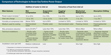
The methods of conditioning the inlet air fall into two general categories:• Addition of water to reduce the inlet-air temperature through evaporation of the water (specific humidity of the inlet air is increased) and increase the total compressor mass flow by the amount of added water. Such techniques include Wet Compression, Evaporative Cooling, and Inlet Fogging.
• Extraction of heat by a heat exchanger to reduce the compressor inlet-air temperature without addition of any secondary fluid: Specific humidity is decreased through condensation as the temperature decreases. Techniques that fall into this category are Inlet Air Chilling and
Refrigeration.
Gas turbine output can be augmented depending on the technology applied and the ambient air conditions. With Wet Compression power plants can achieve up to 20% additional power output, almost independent of the ambient conditions. |
| Effects Achieved by Addition of Water The major effects achieved by adding water are cooling of the air stream and enlarging of the mass flow rate by evaporation of water or moisture. This reduces the amount of work necessary to compress the fluid, providing more power to drive the generator. Another mechanism is an increase in the amount of fuel that is used to raise the lowered temperature of the combustion air to maintain the design turbine inlet temperature. |
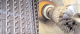 |
| Upgrading gas turbines with an inlet-air conditioning
system significantly enhances power output. Shown is a Wet Compression spray rack. |
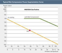 |
| Because Wet Compression acts through several
mechanisms, the gas turbine power gains
are usually higher than those of other inletair
cooling systems |
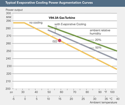 |
| Evaporative Cooling is a passive system and
well demonstrated for improving gas turbine
performance.Chang es are readily predictable
from standard design charts. |
Heat Rate Improvement In recent applications to W501A, W501D5, and W501D5A units, the Wet Compression system has improved (decreased) overall heat rates by at least 1.5 to 2.5%. Test bed studies on the V84.3A-series gas turbine have shown heat rate improvements of 2 to 3%. This represents a
very significant difference compared to direct combustor water injection for NOx control or power augmentation. Direct water injection increases heat rate because energy is lost when water vaporizes.
Emissions Reduction Reduced NOx emissions are attributed to the increased thermal heat capacity because of the water and decreased compressor discharge temperature. Reduction rates of up to 20 to 40% are possible. For engines equipped with dry low-NOx (DLN) combustion systems, the addition of water understandably has a lesser impact, because thermal NOx produced by these combustion system designs is considerably less than with diffusion-based combustion systems. Adding water can also
have a beneficial impact on greenhouse gas emissions. Specific CO2 emissions are also reduced as a consequence of the increased power output.
Operating Temperature Limit Because water is the primary working fluid, there are obvious limitations to the lowest temperature at which such systems can operate. To safely avoid the formation of frost or freezing within the duct, units should not be operated at temperatures below 43°F (6°C). Likewise, the
piping and plumbing of water must have both freeze protection and drain points when installed in climates with ambient temperatures below the freezing point of water. |
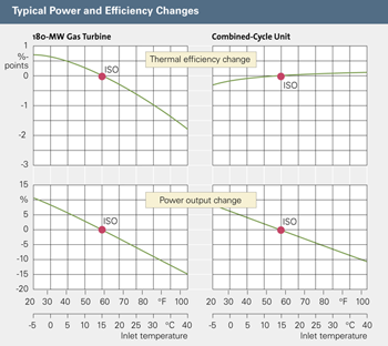 |
| A gas turbine cycle is most affected by
changes in inlet-air conditions while a bottoming
steam cycle is less affected. The power
output of both cycles is affected in the same
way while the effects on heat rate are contrary. |
Wet Compression Using Wet Compression enhances the overall performance of a gas through several mechanisms. First, improvement comes from evaporative cooling of the inlet-air stream. Second, the rapid evaporation of moisture, which takes place in the front stages of the compressor, effectively intercools the compressor. Since the compressor absorbs such a significant amount of power from the turbine, this effect alone substantially improves power and efficiency. Finally,
the additional mass flow caused by the large amount of injected water allows the turbine to generate greater power output.
Main Technical Installations Key design elements of a Wet Compression system focus on the location of the spray racks directly in front of the compressor inlet, the nozzle locations at the rack, and the nozzle spray pattern to uniformly distribute demineralized water at the compressor inlet. The layout and location of the spray racks are established based upon the site-specific configuration of the air inlet system to optimize droplet size and nozzle flow rates to safely produce the required power output.
When water is injected into the compressor inlet, a change occurs in the work
distribution of the compressor. This affects the matching of compressor bleed pressures and turbine pressures and requires adjustments to the turbine cooling circuits.
Control system modifications include additional logic for system response to engine operating conditions that require alarm- or trip-related functions. Emission control updates are required for dry low-NOX combustion systems. In the case of conventional combustion (diffusion)
systems, optimization of combustion-system injection levels may be required and firing-temperature control adjustments are also made.Inlet-duct materials must be resistant to demineralized water. This usually necessitates the application of chemically resistant coatings or materials. Galvanized
materials should either be clad, or protected with chemically resistant coatings.
Evaporative Cooling Evaporative Cooling benefits gas turbine performance as a direct result of reducing compressor inlet-air temperature. Water is not directly injected into the flow stream, but adds to the air flow by adiabatic evaporation. Hence, there is no risk of overspray (like the possible risk with Inlet Fogging) or supersaturation occurring.
Evaporative Cooling is a passive system and best suited to hot, dry climates. This technology is widely used and well demonstrated for improving gas turbine performance. Changes in performance, including heat rate changes, are readily predictable from standard design charts.
Main Technical Installations Surface cooler with honeycomb elements and open, cascading potable-water flow circuit, a low-pressure pump skid, and a storage tank are installed. The cooler elements are positioned in the filter housing in front of or between air-filter stages. No electronic control devices are necessary.
Because continuous wetting of ducts and compressor with droplets does not occur, no additional corrosion protection is required. |
 |
| Power output augmentation depends on the
technology applied and the ambient air conditions.
The impact on the overall performance
of the gas turbine must therefore be
considered in each application. |
Inlet Fogging/Misting Inlet Fogging or Misting are spraying systems that directly spray water into the inlet-air stream. This is a relatively new approach for gas-turbine inlet conditioning, although the process has been around for many years.Like Evaporative Cooling, Fogging and Misting systems are usually placed close to the compressor filter house, the maximum distance away from the face of the compressor inlet. This allows the droplets maximum time to evaporate before entering the gas-turbine rotating components.
It is necessary to maintain an incremental difference of two degrees between the ambient and the compressor-inlet wet bulb temperature, with the compressor inlet temperature being higher.
Otherwise, due to measurement uncertainties, water droplets would be flowing uncontrolled into the compressor. This restriction is the most distinguishing feature between Inlet Fogging and Wet
Compression, because Wet Compression includes additional measures to allow droplets to flow into the compressor.
One drawback of this method is that most duct surfaces will be wetted with demineralized water, which requires measures against duct corrosion. While Wet Compression has to cover only a short distance to the compressor inlet, Inlet Fogging normally requires the modification of a large part of the air inlet, which has to be considered as a required investment.
Power Augmentation by Extraction of Heat Often, the applications for such systems are markets with hot climates that either dry or humid. Inlet air chilling can be accomplished by absorption refrigeration, electric chillers, or possibly ice or chilled-water storage systems. The technology selection requires an evaluation of
plant load and load dispatch requirements, environmental conditions, market energy requirements, and equipment costs. For example, mechanical refrigeration places the largest parasitic loss on the net generated power of the facility, but it allows for a wide range of inlet conditioning without having to introduce secondary fluids.
Peak-shaving facilities can use a thermal storage system, which produces only
minimal plant parasitic losses during the maximum energy requirements, while achieving the same inlet-air temperature as Mechanical Refrigeration. During non-peak periods the unit can generate chilled water (or ice) which can then be used during the critical peak periods. However, as
described later, both these systems are likely to be expensive, and may require a large installation area. Inlet cooling of the air can be achieved by using two distinct approaches: Mechanical Refrigeration and Absorption Chilling.
Mechanical Refrigeration Mechanical Refrigeration is a technology for cooling down the inlet air and uses the well-known and proven method of a refrigeration cycle. The heat is extracted from the compressor inlet air via cooling coils which are part of the evaporator of a separate vapor-compression cooling cycle,
working with a freezing mixture.Theoretically, inlet-air temperatures below 0°C can be achieved but in order to avoid inlet icing, 6°C is considered the lower limit. As the inlet air is cooled down
and humidity reaches 100%, moisture in the air is condensed. Further cooling consumes
a lot more energy because the condensation of moisture has a negative effect on the overall heat rate.
The drier the air, the less power vaporcompression cooling consumes, and the better the overall heat rate. A disadvantage of mechanical refrigeration is the comparatively high electrical power demand to run the separate vapor-compression cooling cycle.
Absorption Chilling Cooling by Absorption Chilling is also a well-known and proven method. The process of cooling down compressor inlet air is comparable to mechanical refrigeration.The main differences between both
are a "thermal” compressor instead of a mechanical one and a cooling cycle with absorber, solvent pump, and ejector. The energy to run the thermal compressor is the heat extracted from exhaust
gas of the turbine via the ejector. If waste heat is used, the energy balance will be much better compared to a cooling cycle with an electricity-driven mechanical compressor.
Effect on a Combined-Cycle Process In a combined-cycle power plant, the gas turbine is most affected by changes in inlet air conditions. For example, a decrease in the compressor air inlet temperature of 30°K on a 250-MW combined-cycle block yields a power enhancement of nearly 30 MW at the gas turbine and and
only 3 MW at the bottoming steam cycle. However, in combined-cycle applications, the existing hardware can be very different, so the effect on power enhancement must be determined on a case-bycase
basis. Generally, however, heat rate improvement (decrease) at the gas turbine is expected, but this positive benefit can be compensated downward by the steam cycle under negative circumstances. |
| Informations data |
| Siemens power journal online |
Back

|
|