Inlet Fogging Systems
AMCO provides extensive engineering, manufacturing, and application knowledge of inlet direct spray cooling systems for the gas turbine industry.
AMCO has thousands of high-pressure systems in a variety of industrial applications and is a world leader in the industry.
AMCO Fogging systems augment efficiency of gas turbines :
- Increase turbine output (up to 20%)
- Reduce heat rate
- Reduce NOx emissions
Why Select an AMCO Turbine Inlet Cooling System?
- Negligible inlet pressure drop
- AMCO has over 100 years fog system manufacturing experience
- Approved supplier to new gas turbines
- Typical cooling increments of 0.55 °C
- All 316L stainless steel construction
- High pressure delivery system up to 207-bar
- Full penetration TIG welding
- PLC Controls manage multiple cooling zones
- Fast and easy installation; only 2-3 days down-time.
- Engineering services
- Superior nozzles
How it Works
1. The AMCO Direct Spray Cooler consists of one or more positive displacement pumps that pressurize demineralized water to 207-bar..
2. The pressurized water is fed into a series
of seamless stainless steel headers connected to stainless steel nozzle manifolds, typically located immediately downstream of the high efficiency filters.
3. Specialized AMCO nozzles atomize the pressured water into ultra-fine droplets that evaporate quickly and efficiently even in the most humid conditions. |

|
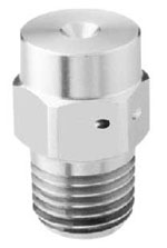
Swirl Jet Nozzle
|
-
Higher nozzle flow - fewer nozzles required
-
90% droplets mass is less than 20 microns see Swirljet Nozzle table
-
Smaller droplets - better evaporation
-
Durable design - no impaction pin
-
Safety lock wired to the manifold using aircraft industry standard locking methods
-
Nozzle adapters are attached to seamless 316L stainless steel tubing via a full penetration TIG weld in accordance with ANSI-B31.1 standards
-
Provides increased reliability, less maintenance, and longer service life
|
|
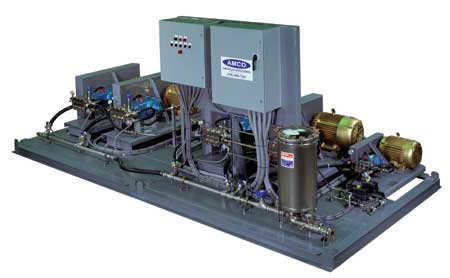
Pump Skid
High Pressure Skid and Inlet Nozzle Array
The AMCO direct spray inlet cooling system is the pump and control skid, and inlet nozzle array engineered to meet or exceed the highest industry standards. In the example the AMCO skid is providing 60 GPM with (6) cooling zones (32) nozzle lines, allowing (33) separate stages of cooling at increments of 1.3°F (Inlet Side View Drawing, Spray Zone Flow Table, and Cooling Increment Table). |
|
P&ID Process and Instrumentation Diagram
|
No.
|
Description
|
1 |
Filter |
2 |
Low-Pressure Gauge |
3 |
Flow Meter/Transmitter |
4 |
Low-Pressure Transmitter |
5 |
Low-Pressure Solenoid Valve |
6 |
Pressure Relief Valve |
7 |
High-Pressure Pump |
8 |
Pulsation Dampener |
9 |
Pressure Control Valve |
10 |
Temperature Transmitter |
11 |
High-Pressure Gauge |
12 |
High-Pressure Transmitter |
Inlet Side View
 |
Back
|
|